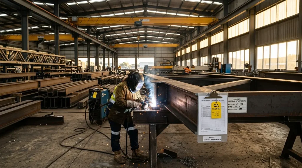
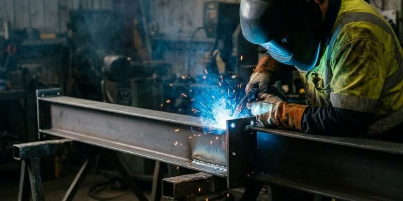
A welder in protective gear joins steel beams with bright sparks flying in a workshop.

Steel Beam vs LVL for a Melbourne Knock-Through: Cost, Span and Fire Rating Compared

The short answer: for most Melbourne knock-throughs, LVL is cheaper to buy but steel wins once the clear span passes roughly 4 to 4.5 metres, once you are carrying a second storey, or once ceiling height matters. As a rough 2026 guide, an LVL beam for a typical wall opening costs around $20–$76 per lineal metre to supply, while a fabricated steel UB typically lands in the $200–$500 per lineal metre range supplied and installed. The gap looks big on paper — but on longer spans, LVL sections get so deep that they eat your ceiling, need doubling or tripling up, and can end up costing more once labour and propping are counted. This guide breaks down when each one actually makes sense.

If you already know you need steel and want to sanity-check the section size, our residential steel beam span tables guide explains how the sizing logic works. If you want the fabrication and installation side, see residential structural steel.

Steel vs LVL at a Glance

FactorSteel UB (Universal Beam)LVL (Laminated Veneer Lumber)
Typical supply costHigher per metre — broadly $200–$500 per lineal metre supplied and installedFrom roughly $20–$30/lm for common sizes; deep sections (300×63) around $76/lm at retail
Practical span for a knock-throughComfortably 4–8 m+ in a single sectionEfficient up to ~3.5–4.5 m; beyond that, sections get very deep or need multiple plies
Section depth for the same spanShallowest option — a 200–250 UB often does what a 300–400 mm LVL cannotDeeper for the same load; can force a downstand bulkhead
Weight and handlingHeavy — often needs a crane, lifting frame or several riggersLight — two carpenters can usually lift it
Installation tradeSteel fabricator + riggers (or builder with lifting gear)Carpenter
Crane required?Often yes for spans over ~5 m or difficult accessRarely
Fire performanceNon-combustible, but loses strength in fire — may need intumescent coating or fire-rated linings where the NCC requires itCombustible, but chars predictably; achieves FRLs via sacrificial thickness or fire-rated plasterboard
Termites and moistureImmune to termites; needs corrosion protection in exposed or coastal settingsNeeds H2S treatment for termites; must stay dry
Long-term deflection (creep)Effectively none — steel does not creep under sustained loadTimber creeps; long spans can develop visible sag over years
Drilling services through it laterWeb penetrations must be designed by an engineer — do not cut on siteLimited drilling allowed within the manufacturer’s rules
Connection to existing structureWelded or bolted end plates onto posts/padstones — engineered and compactNailed/bolted timber connections — simple but bulkier
Lead timeFabricated to your engineer’s drawings, typically daysOff the shelf same day for stock sizes

The Real Question Is Span, Not Price Per Metre

Comparing dollars per metre is the mistake almost everyone makes at the start. The right sequence is: span and load first, then depth, then price.

Every beam in a knock-through is sized by a structural engineer against AS 1684 (timber) or AS 4100 (steel) for your specific span, the load above it (roof only, or roof plus a first floor), and how much deflection is acceptable. Two things happen as spans grow:

  1. LVL depth grows fast. A single-storey opening of 3 m might be handled by a 240×45 LVL. Push the same situation to 5.5 m with a floor above, and you are suddenly looking at doubled or tripled 400 mm-deep LVLs — which means a bulkhead hanging 200 mm+ below your 2.4 m ceiling, right where you wanted an uninterrupted open plan.
  2. Steel stays shallow. Because steel is far stiffer per millimetre of depth, a UB can often sit entirely within the existing ceiling/floor zone. That is why the beams in most “invisible” open-plan renovations you see in Brighton, Kew or Toorak are steel — the beam is up in the floor structure, not hanging below it.

As a rule of thumb for Melbourne homes (your engineer’s calculations always govern):

  • Up to ~3.5 m, single storey above: LVL is usually the economical pick.
  • 3.5–4.5 m, or any second storey above: genuinely line-ball — get both priced.
  • Over ~4.5 m, or where you want a flush ceiling: steel is almost always the answer.

Our residential steel beam span tables show indicative UB and PFC capacities by span if you want to sanity-check what your engineer specifies.

When LVL Is the Better Choice

To be fair to timber — and we say this as a steel fabricator — LVL genuinely wins in these situations:

  • Short spans in single-storey homes. A 2.4–3 m opening under a roof-only load rarely justifies steel. An off-the-shelf LVL, two carpenters and an afternoon will do it.
  • Tight access with no crane option. Rear extensions in narrow inner-suburb blocks (think Richmond or Northcote terraces) where nothing heavier than what two people can carry will get through.
  • Fixing convenience. Carpenters can nail joist hangers and top plates straight into LVL. Fixing timber to steel needs pre-drilled cleats or a timber top plate bolted on — all solvable, but it must be on the drawings.
  • Budget-critical jobs where a bulkhead is acceptable. If you do not mind a boxed-in beam below the ceiling, LVL keeps both material and labour costs down.

When Steel Is the Only Sensible Option

  • Spans beyond ~4.5 m. The full-width rear knock-through — kitchen, dining and living opened into one space across a 5–7 m wall — is steel territory. LVL alternatives at these spans become impractically deep and heavy.
  • Two storeys above the opening. Point loads from an upper floor and roof concentrate fast. Steel’s capacity keeps the section compact and the connections engineered.
  • Flush ceilings. If the design brief says “no bulkhead”, the beam has to sit within the floor zone, and that almost always means a UB with joists hung off the web.
  • Steel posts already in the design. If the engineer has specified SHS posts at each end, a steel beam with bolted end plates gives cleaner, stiffer connections than mixing timber onto steel.
  • Future-proofing against sag. Steel does not creep. On a wide opening, an LVL sized to the code minimum can still develop a few millimetres of visible deflection over a decade — enough to crack cornices. Steel holds its line.

For a deeper dive on the economics across whole builds rather than single openings, see our earlier analysis of steel vs timber building economics.

Full Cost Comparison for a Typical Knock-Through

Here is how the whole job compares for a common Melbourne scenario — removing a 4.5 m load-bearing wall between kitchen and living in a single-storey brick veneer home, roof load only, at the upper end of what LVL handles comfortably. Figures are indicative 2026 ranges, ex GST, and are not a quotation; every site differs.

Cost itemLVL solutionSteel UB solution
Structural engineer’s design & computations$800–$1,800$800–$1,800
Building permit (where required)$600–$1,200$600–$1,200
Beam supply$150–$500 (may need 2 plies)$900–$2,250 (roughly $200–$500/lm over 4.5 m)
Fabrication (end plates, cleats, primer)n/aIncluded in the fabricated rate
Temporary propping & needle beams$400–$900$400–$900
Installation labourCarpenter: $500–$1,200Riggers/installers: $800–$2,500
Crane or lifting gearRarely needed$0–$1,500 depending on access
Making good (plaster, cornice, paint)$800–$2,000$800–$2,000
Typical all-in range$3,500–$7,500$5,000–$10,000

Two honest observations from that table:

  • On a mid-size span, the total gap between LVL and steel is usually $1,500–$3,000, not the multiples the per-metre prices suggest. Engineering, permits, propping and patching cost the same either way.
  • The steel number buys you a shallower beam, zero creep, and no termite or moisture caveats. Whether that is worth the difference is a design decision as much as a budget one.

These ranges align with what Melbourne wall-removal specialists publish for complete jobs — typically $4,000–$10,000 all-in depending on span, load and access.

What We Would Recommend by Melbourne House Type

  • Post-war brick veneer (Box Hill, Sunshine, Footscray): ceilings are often 2.4 m and every millimetre counts. Steel UB in the ceiling zone for anything over 4 m; LVL is fine for smaller pantry or hallway openings.
  • Period weatherboard or terrace (inner north and inner west): access is the deciding factor. If a crane cannot get in, a steel beam can still be spliced and site-bolted — talk to the fabricator before assuming LVL is the only option.
  • Double-storey 80s–2000s homes (Doncaster, Glen Waverley): anything carrying the first floor should be priced in steel first. The LVL equivalent is usually too deep to hide.
  • High-end renovations (Brighton, Toorak, Kew, South Yarra): almost always steel — flush ceilings, wide spans, and often exposed black-steel feature beams as part of the architecture.

Frequently Asked Questions

Is a steel beam always stronger than LVL?

Size for size, yes — steel carries far more load for the same depth. But “strong enough” is what matters, and your engineer will size either material to do the job. The real differences are depth, deflection over time, and installation method.

Can I use LVL to remove a load-bearing wall in a two-storey house?

Sometimes, on short spans. But once an upper floor bears on the opening, LVL sections get deep and heavy quickly. Most Melbourne engineers default to steel for two-storey knock-throughs over about 3.5 m.

What size steel beam do I need to replace a 4-metre wall?

It depends entirely on the load above. As an indication only, single-storey roof loads at 4 m often land around a 200 UB, while floor-bearing situations step up from there. Your engineer’s computations are the only numbers that count — our span tables page explains how the sizing logic works.

Is LVL cheaper than steel?

As a raw material, yes — common LVL sizes retail from roughly $20–$76 per lineal metre, while fabricated and installed steel typically runs $200–$500 per lineal metre. On a whole-job basis the gap narrows to $1,500–$3,000 for a typical opening, because everything around the beam costs the same.

Do steel beams need fireproofing in a house?

In most detached-home knock-throughs, no special treatment is required beyond standard plasterboard linings — but where the NCC does require a fire resistance level (for example near boundaries or in multi-residential work), steel needs intumescent coating or fire-rated encasement. Your building surveyor will confirm what applies.

Will an LVL beam sag over time?

All timber creeps under sustained load. A correctly sized LVL stays within code deflection limits, but on wide spans that can still mean a visible few millimetres after years — one reason steel is preferred where a dead-flat ceiling line matters.

Can a steel beam be installed without a crane?

Often, yes. Shorter beams can be lifted with mechanical jacks and skates, and longer beams can be designed as bolted splices so they go in as two lighter pieces. This is a fabrication decision — raise access constraints before the beam is detailed.

Who installs the beam — a carpenter or a steel fabricator?

LVL is carpenter territory. Steel beams are typically supplied and installed by a fabrication team with licensed riggers, coordinated with your builder for propping and making good. AC Steel handles residential steel beam supply and installation across Melbourne.

Not sure which way your opening should go? Send us your engineer’s drawings — or just the span and what is above it — and we will tell you straight whether steel is worth it for your job or whether LVL will do. Book a 15-minute beam check with our fabrication team.
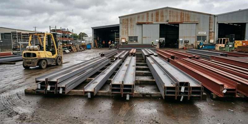

Rows of steel beams stacked on wooden pallets in a wet industrial yard with a yellow forklift nearby.

From CAD Shop Drawing to Installed Steel: How Builders Avoid RFI Delays with Integrated Fabrication

On a build program, steel rarely slips because someone cut a beam wrong — it slips because a question sat unanswered. Every RFI, or request for information, is a pause: a detail that was ambiguous on the drawing, a connection the engineer had not yet signed off, a clash nobody caught until the crane was already booked. The fix is not heroics on site; it is detail and coordination upstream. Thorough shop drawings, early engagement with the engineer and architect, and a single team carrying the job from CAD through to erection remove most of the back-and-forth before it can cost you a week. This article walks the six stages from CAD shop drawing to installed steel, shows where RFIs are born, and explains why combining fabrication and installation under one interface keeps the program moving — always within the boundary that connection design and construction categories stay with the structural engineer.

What an RFI Actually Costs a Build Program

Start with what an RFI is: a formal request for information — a builder, fabricator or trade asking a designer to clarify or resolve something the documents left ambiguous. It sounds like paperwork, but the hidden cost is time, not paper. Each open RFI can idle a fabrication slot, a delivery, or a crane booking while everyone waits on an answer.

Steel is unforgiving of ambiguity. Unlike some trades that can fudge things on site, a mis-detailed connection or a missing hole cannot really be worked around in the field — it goes into a rework loop. And RFIs cluster at the seams, right where drawings meet reality: connection details, setout, service penetrations, and the interfaces between steel and other trades. Beneath all of it runs a pattern: most steel-related delays trace back not to workmanship, but to information that was unclear or unconfirmed before fabrication started.

From here this article does two things: map the six stages from CAD to erection, then show which coordination moves shrink the RFI pile — see how structural steel moves from drawing to install.

The Six Stages: From CAD Shop Drawing to Erected Steel

Stage 1 — Design intent and the engineer’s drawings. The structural engineer’s design (framed by AS 4100 for steel structures) sets loads, member sizes and connection concepts. This is where the whole chain begins.

Stage 2 — Shop and detailing drawings. The in-house CAD team turns design intent into fabrication-ready detail — every hole, cleat, weld and mark number lands on the drawing.

Stage 3 — Approvals and coordination. The engineer and architect review the shop drawings; clashes with other trades get resolved on paper, not on site.

Stage 4 — CNC fabrication. Cutting, drilling and certified welding to the detailed drawings, under the AS/NZS 5131 fabrication framework.

Stage 5 — Delivery and sequencing. Members are marked and staged to match the erection sequence, so the right steel arrives in the right order.

Stage 6 — On-site installation. The fabrication and installation crew erects to the approved drawings — with far fewer surprises when Stages 2 and 3 were done thoroughly.

Where RFIs Are Born — and How Good Shop Drawings Prevent Them

RFIs do not appear out of nowhere; they are born in a few very specific places. Ambiguous connections are the number-one source: a detail that shows “typical” without the specific cleat, bolt group or weld invites an RFI mid-fabrication — good detailing spells it out. Setout and datum errors are the second: unclear grid lines and levels cause clashes at erection, and the shop-drawing stage is where they should be caught.

Missing penetrations are just as common: services routed through beams that were never holed means site cutting, rework, and an engineer sign-off request under load. Trade interfaces are a classic RFI hotbed — steel meeting concrete, timber, precast or facade, where an undocumented interface will bite sooner or later. And revision control matters too: working from a superseded drawing generates avoidable RFIs, whereas a single detailing source keeps everyone on the current issue.

There is a quieter cost here, too. Each of these RFIs tends to arrive at the worst possible moment — when the fabrication slot is booked, the delivery is scheduled, and the crew is standing by. A question that would have taken a minute to answer at the drawing table now stops a chain of committed resources, and the delay ripples into every trade that was waiting on the steel to go up.

Tie these together and you get an upstream principle: an hour resolving a detail in CAD routinely saves days of waiting once the steel is on the truck. Detail is cheaper than delay.

Early Engineer and Architect Coordination

Engaging before fabrication locks in is the key to saving money. Reviewing shop drawings with the engineer and architect early resolves questions while changes are still cheap; once the steel is made, the same change costs many times more. And there is a boundary that must hold: the fabricator details and builds to it, but connection design and construction-category calls remain the structural engineer’s responsibility and sign-off. The fabricator details it and builds it, but does not replace it.

Clash detection on paper — coordinating steel against services, facade and other trades during detailing — prevents the far more expensive on-site version. The ideal is one conversation, not a chain: early three-way alignment between builder, engineer and fabricator shortens the question-and-answer loop that RFIs formalise. Reference standards and details with their version and date so approvals stay traceable — see the published AS 4100 standards guide. For homes and townhouses, structural assessment and final sign-off sit with the engineer — see residential structural steel.

Why Combining Fabrication and Installation Removes Friction

A female engineer in a suit sits at a desk reviewing architectural blueprints with a white hard hat nearby.

One interface, one accountability. When the team that detailed and fabricated also erects, there is no gap for information to fall through. A split model — fabricate, then subcontract the install — creates a coordination seam by design, and questions, along with blame, accumulate in that seam.

An integrated team marks and delivers steel in erection order, because the same team is the one putting it up. Sequencing stops being a guess and becomes a shared plan: the members that go up first are made and staged first, and the crane is never left waiting on a piece that is still on the bench. And when an issue does arise — a beam that fouls a service run, a cleat that needs a field adjustment — a site query goes straight back to the people who drew and made the piece, rather than around a subcontract chain where each link adds a day. Removing the fab-to-install handover typically takes coordination time out of the schedule — see how steel fabrication works end to end. Certified welding and CNC fabrication under one roof also keep quality records consistent and traceable, from drawing to installed member, so that if a check is ever needed the paper trail already lines up with the steel on the ground.

A Realistic RFI-Reduction Checklist for Builders

Lock the detailing scope early. Before fabrication starts, confirm who details, to what standard, and how revisions are controlled. Insist on connection clarity. No “typical” without the specific detail; every connection resolved on the shop drawing and engineer-signed. Coordinate penetrations upfront. Get services and holes onto the drawings before cutting, not after.

Align the erection sequence. Agree the delivery order against the site program so steel lands the moment the crane is ready, not a fortnight early to sit rusting in the mud, and not a day late while the crew stands idle. Keep one current drawing set. A single controlled source, with superseded issues clearly withdrawn, prevents the avoidable RFIs that spread when two trades are quietly working from different revisions. Choose an integrated partner where it helps. For complex custom homes and multi-unit work, a single structural steel interface reduces the coordination surface and shortens the loop when a question does come up — but it never replaces the engineer’s design role.

Planning Winter Detailing for a Spring Steel Program

Winter is detailing season. Mid-winter is when the CAD and coordination work is best done well, so that fabrication and erection can run cleanly once the weather turns. Raise and close the hard questions now, on paper, rather than in spring when the crane clock is already running — that is what front-loading the RFIs means.

Confirming engineer availability early matters too: sign-off on connections and categories can be a bottleneck, so book that review into the winter program. Use the quieter months to fabricate and mark ahead against a confirmed erection sequence. And plan delivery and craneage windows around Melbourne’s wet winter conditions to protect the erection dates. In the end, an early conversation with an integrated fabricator sets the detailing and coordination up before the program tightens — get in touch.

The difference between a steel program that holds its dates and one that drifts is rarely dramatic — it is a stack of small questions answered early instead of late. Detailed shop drawings, genuine coordination with the engineer and architect, and a single team carrying the job from CAD to erection turn most would-be RFIs into non-events. If you are scoping a residential, townhouse or commercial build for the coming season, now — in the quiet of winter — is the moment to get the detailing and coordination right, so spring is about erecting steel, not chasing answers. Talk to A.C. Steel Construction about an integrated approach to your next project.

This article is general guidance only; connection design, construction categories and final structural sign-off remain the responsibility of your registered structural engineer, and standards should be referenced in their current version and date.

Two construction workers in hard hats reviewing building plans and a tablet on a construction site

A Residential Builder’s Guide to Steel Beam Span Tables — When You Can Estimate from the Manual, and When You Need an Engineer

Every residential builder doing extension work in Victoria has used a span table. The OneSteel Hot Rolled and Structural Steel Products manual, the BlueScope DuraGal design guide, the ASI residential steel application charts — each one comes with span charts that turn “can a 200UB22 carry the roof and first-floor over a 4.2 m opening” or “does a 250UB31 need a mid-span column over 5.5 m” into a 90-second estimate.

But a span table is not a structural design. It is a budgeting tool, a preliminary sizing tool, and a tool for the conversation with the engineer that follows — not a substitute for the engineer. Builders who treat span tables as a stand-in for engineering sign-off eventually meet trouble at permit review, at insurance time, or at the on-site moment when an actual load lands somewhere the table did not anticipate. This article draws the boundary that often gets blurred in everyday practice — where a builder can responsibly use a span table, and where the drawings have to be sent to an RPEng-registered structural engineer for calculation and sign-off. The audience is residential builders, draftspersons and owner-builders in Victoria and New South Wales doing single-storey extensions, open-plan renovations and load-bearing wall removals.

What a span table actually gives you

To understand the boundary, it helps to understand what is sitting behind the table.

Every residential steel beam span table is built on a fixed set of assumptions: a particular section (say 200UB22), a steel grade (typically 300PLUS or 350), a single simply-supported span with no continuity, a defined load combination (such as “single-storey roof plus one floor with standard imposed load”), and a target deflection limit (commonly span/250 or span/300). Within those assumptions, the maximum allowable span on the chart is valid.

For a single-storey extension where you are putting a single 4 m beam over an internal opening, carrying roof truss loading from above and no unusual point loads or cantilevers, the table’s preliminary sizing is genuinely useful. The builder can put that estimate into the customer quote, the material pre-order, and the first conversation with the engineer. It saves time.

Span tables also help builders sense-check proportion. If a client wants to span a 6 m first-floor opening on a 150 PFC, the chart tells you in one glance that the combination is not real — and “filtering out the impossible early” is one of the most useful things a span table does.

What a span table does not give you

What the table delivers is the answer to the question the chart assumes you are asking. The moment your project drifts past those assumptions, the table goes silent and the work has to move to a structural engineer.

The first boundary is continuity. Span tables are simply-supported single-span. The moment a beam is continuous over two or more spans — for example, an 8 m beam landing on a mid-column and behaving as two 4 m sections — the distribution of bending moments at midspan and over the support changes completely. The simply-supported value is conservative for span moments but actively misleading for support reactions, which can mean the column or footing underneath is incorrectly sized.

The second boundary is cantilevers. The chart values are for beams supported at both ends. A cantilever bending moment behaves differently — a 1.5 m cantilevered balcony beam can require a heavier section than a 6 m simply-supported beam, because the root moment is not balanced by support at the far end. Cantilevers always go to an engineer.

The third boundary is point loads. Span tables assume uniformly distributed loading. The moment a beam carries a 200 kg air-conditioning unit, takes the load of a column landing from the floor above, or receives a secondary beam transferring concentrated load from another bay, the loading profile is no longer what the chart calculated.

The fourth boundary is non-standard or high imposed loads. Imposed load is not one number. Residential floors, balconies, garages, roof gardens, storage rooms, plant rooms, solar array zones — each carries a different prescribed value under AS/NZS 1170. Standard residential floor sits at 1.5 kPa; balconies at 2.0 kPa; roof gardens and storage areas climb to 3.0 kPa or higher. A span table assumes a “default residential combination” and stops being usable as soon as the project departs from it.

A woman in a suit reviews architectural plans with a pen while a computer screen displays a 3D model nearby.

The fifth boundary is lateral stability. A tall, slender UB section without floor restraint above will fail by lateral-torsional buckling well before it reaches its calculated bending capacity, and the chart’s allowable span has to be drastically reduced. The “fully laterally restrained” assumption baked into most charts fails in many practical residential cases — for example, an exposed beam running below a living room ceiling with no slab or truss bracing it laterally must be re-evaluated as unrestrained.

The sixth boundary is connections. How two beams join, how a beam sits onto a brick pier, how it connects down to timber trusses, whether a baseplate and anchor bolts are required — these belong to AS 4100 Section 9 and span tables touch none of them.

The seventh boundary is fire resistance. Multi-unit residential and commercial projects require structural steel to carry an FRL under the NCC, which can involve intumescent paint, fire boards or section upsizing. Span tables do not consider FRL at all.

The eighth boundary is construction categoryCC1, CC2, CC3. AS/NZS 5131 sorts steelwork by consequence class, with most single-storey residential work in CC2 and multi-unit work in CC3. The CC class drives fabricator qualification, welder certification, inspection frequency and documentation requirements. None of that is something a builder selects from a span table. It is something the engineer determines under AS 4100, AS/NZS 1170 and AS/NZS 5131, and writes into the design notes.

A practical decision flow

Translated into a checklist a builder can actually use on site or at budgeting time, the boundary works like this.

First, ask whether the beam is single-span, simply-supported, uniformly distributed loaded, laterally restrained by the floor above, and inside the default single-storey residential load combination. If all five hold and the span sits in the 3 to 5.5 m residential range, the span table’s estimate is appropriate for budgeting and for the early engineer conversation.

Second, anything that involves removing a load-bearing internal wall in an open-plan renovation, converting an external wall to a full-height glass slider, exposing a 6 m or longer beam below a ceiling, spanning a first-floor opening greater than 4.5 m, cantilevering a balcony beyond 1.2 m, or carrying a roof garden or large solar array — sends the drawings to an engineer.

Third, anything that involves multi-span continuity, point loads, cantilevers, lateral-torsional buckling risk, baseplate design or anchor bolt design — engineer, and RPEng-registered.

Fourth, on CC2 work the structural drawings carry the engineer’s signature and stamp; on CC3 work, in addition to design sign-off, fabrication and welding follow the AS/NZS 5131 CC3 process, including non-destructive testing and process inspection records.

Fifth, the engineer’s drawings go to the fabricator’s in-house CAD team for shop drawings. Shop drawings are not the engineer’s deliverable — the fabricator produces them and the engineer reviews and signs them back. This step translates “design intent” into the cut-list, weld-list and assembly sequence the workshop can actually execute.

Why a builder’s own table-reading rarely saves money

Owner-builders and less-experienced small builders sometimes treat “I’ve done a dozen of these, I can just pick the section off the chart myself” as a reasonable shortcut. The cost layers behind that view are worth being clear about.

The first is compliance cost. Victoria’s building permit process requires a structural engineer’s design support for Class 1a residential work above a certain area or involving structural alterations. If a builder picks the section from the chart, the surveyor will require an engineer’s calc anyway. If the calc comes back and the picked section is wrong, the project either re-drafts, replaces the beam, or argues for retention of the chosen section — none of which is cheap.

The second is insurance cost. Most builders’ home warranty insurance and public liability cover require structural elements to be designed by a qualified engineer. If a builder-picked beam ever shows signs of distress — settlement, cracking, connection movement — insurers commonly cite “not engineer-designed” as grounds for declining cover.

The third is rework cost. Once a structural steel beam is cut, welded and installed into the wall, discovering it is undersized is rarely a quick fix. Removing an installed lintel and replacing it pulls in secondary beams, floor framing, roof framing and surrounding wall work — typically 20 to 50 times the cost of the engineer’s original fee.

The fourth is liability cost. Building industry liability does not evaporate in five years. A 15-year-old steel beam that develops capacity issues triggers an investigation whose first question is whether the original work carried engineer sign-off. Builders without that sign-off carry personal liability.

A workable collaboration model

The builders we work with most often are small-to-mid residential outfits doing extensions and major renovations in the AUD 150,000 to 2.5 million range. At that scale, projects do not usually carry a dedicated project manager — structural steel coordination falls to the site supervisor or to the builder personally. A smooth collaboration model usually looks like this.

At the budgeting stage, the builder uses a span table to set a preliminary section range and quotes the client a “structural steel including fabrication and installation in the range AUD X to Y” envelope. The client is told explicitly that the engineer’s final section sizing may move within that range.

At the design stage, the architect’s or draftsperson’s preliminary drawings go to an RPEng-registered structural engineer, who produces structural drawings and calculations. This usually takes one to three weeks; complex jobs longer. When the builder and the engineer have an established working relationship, that compresses to within a week.

At the quoting stage, the engineer’s structural drawings go to the fabricator for shop drawings and a firm quote. Our residential structural steel service and our steel beam fabrication and installation service typically turn structural drawings into shop drawings and a binding quote inside 5 to 10 working days.

At the fabrication and installation stage, the work follows the AS/NZS 5131 process for the project’s CC class — fit-up inspection, weld inspection, transport, on-site rigging. Most residential work is CC2; shop drawings go back to the engineer for review, welding is performed by certified welders, and the fabricator issues a Certificate of Compliance on completion.

The boundary works in the builder’s favour

A lot of builders treat “needs an engineer’s sign-off” as an extra cost. Read the other way, it is a protection. Once the engineer signs the drawing, structural responsibility sits with the engineer, and the builder’s role moves back inside the clean limits of “build to the drawings, fabricate to the standard, deliver against the contract”. A builder who does everything themselves carries design, build, compliance and insurance risk in one package; a builder who knows what to send to the engineer, what to estimate themselves, and what to send to the fabricator runs projects faster, more reliably and more cheaply.

Span tables are useful tools for builders, provided they are treated as estimating tools rather than as design documents. AS 4100 and AS/NZS 5131 assign responsibility along the chain from mill to handover, and the cost of crossing that chain casually is much higher than the cost of working with it. The structural role of steel in residential work has grown noticeably in recent years — bigger openings, more exposed expression, more complex open-plan layouts — and the boundary matters more in that environment, not less.

Span table conventions, CC class assignments, RPEng sign-off and Victorian building permit processes in this article reflect current practice in the Australian residential structural steel market; specific section choice, connection design and compliance requirements must be confirmed by the project’s RPEng-registered structural engineer and against the latest editions of the relevant standards published by the ABCB, Standards Australia and Engineers Australia. This article is not engineering advice and does not replace design or sign-off by an RPEng-registered structural engineer.

Stacks of steel I-beams in a large industrial warehouse with polished concrete floor and bright windows.

AS 4100 vs AS/NZS 5131 — Which One Does a Melbourne Builder Actually Need to Understand?

AS 4100 vs AS/NZS 5131 — Which One Does a Melbourne Builder Actually Need to Understand?

Open almost any structural steel shop drawing on a Melbourne project and somewhere on the title block you will see two standards cited side by side: AS 4100 and AS/NZS 5131. They sit there as if everyone already knows what each one does. Most builders do not — and that is not a criticism. Until 2016, the second of those barely existed as a separate document, and the way responsibilities now divide between them has not been explained particularly well to the people who actually run building sites.

This article is not a structural engineering tutorial. It does not pretend to replace the work that an RPEng does when calculating a beam, or the judgment a building surveyor brings to a sign-off. It is written for the people standing on site reading a shop drawing — the custom home builder, the townhouse developer, the site manager — trying to work out what these two standards mean for their week. The short version is that one is a design standard and the other is a fabrication and erection standard. Once you can hold that distinction in your head, a surprising amount of the rest of the documentation falls into place.

The Construction Category framework inside AS/NZS 5131 — CC1 through CC4 — quietly determines how thick the documentation pack is going to be, which welder qualifications the shop needs, and how much inspection work has to happen before steel can be signed off. Builders who learn to read those categories early generally save themselves a fortnight of friction later.

1. The 30-Second Version Most Builders Never Get Told

AS 4100 is the steel structures design standard. Its job is to tell the structural engineer how big the beam needs to be, what the connection capacities should be, and how the structure should behave under load. The output of AS 4100 lives in the engineer’s calculation pad and on the structural drawings.

AS/NZS 5131 is the structural steelwork fabrication and erection standard. Its job is to tell the fabricator how to make that beam — what welding qualifications apply, what tolerance bands are acceptable, what inspection regime governs the welds — and to tell the erector how to put it together on site. Its output lives in shop drawings, Inspection and Test Plans, welder qualification records, mill certificates, and the erection methodology.

Both standards live on the same project because a project has to be designed correctly and then made and assembled correctly. A builder does not need to compute a member capacity to AS 4100 — that is the engineer’s job. But a builder absolutely does need to read the AS/NZS 5131 references on a shop drawing, because those references tell you what your fabricator has to deliver and what paperwork has to be on file before the building surveyor signs anything off.

2. A Bit of History — Why They Used to Live in One Book

Before 2016, AS 4100 carried fabrication and erection content inside itself. Designers, fabricators and inspectors all worked from the same document, and the distinction between a design rule and a fabrication rule was blurred. AS/NZS 5131 was then published as a standalone fabrication and erection standard, with AS 4100 amended to remove most of its overlapping content and refer to 5131. Subsequent amendments have put more shape around shop drawing requirements, Inspection and Test Plans, and welder qualification records.

For a builder, today’s structural steel documentation pack is noticeably thicker than it was a decade ago, and the responsibilities for delivering each part of that pack are more clearly assigned. When the title block cites both AS 4100 and AS/NZS 5131, it is telling you that the design has been done to one standard and the make-and-assemble has been done to the other. A.C. Steel Construction’s in-house CAD team carries a fair amount of this load on behalf of builders — the shop drawing set, welder qualifications, Inspection and Test Plan, mill certificates and welding procedure references arrive in a package organised against AS/NZS 5131 expectations rather than left for the builder to assemble from fragments.

3. CC1 to CC4 — The Number That Decides Your Document Stack

The single most important number on a structural steel shop drawing — from a builder’s point of view — is the Construction Category. AS/NZS 5131 defines four. CC1 covers the lowest-risk work: simple, small, low-consequence-of-failure structures. CC2 is the workhorse category for most residential and smaller commercial projects. CC3 covers higher-risk work — multi-storey residential, commercial buildings, more public-facing structures. CC4 is reserved for the highest-risk work: large public buildings, bridges, specialised industrial structures.

The category is assigned by the structural engineer based on the project’s risk profile. Once that number is set, it determines the welder qualifications required, the level of NDT, the documentation depth, and the tolerance bands. A CC3 job is not just a CC2 job with more paperwork — it is a different operating regime for the fabricator, with implications for material selection, weld quality and inspection effort.

For builders, the question to ask early — at contract stage if possible — is simple. What Construction Category has the engineer assigned to this project? If the answer is not clearly written on the structural drawings or in the specification, that is a conversation to have with the engineer before anything is fabricated. As a rough indication of where projects tend to land, a two-storey custom home with significant cantilevers or long spans often sits at CC2, and townhouse rows or low-rise residential blocks can be assigned anywhere from CC2 to CC3 depending on the engineer’s read of risk. The final call is the engineer’s.

4. What a Compliant Shop Drawing Set Should Contain

Construction worker in safety gear holding blueprints while looking at a building site under construction

A shop drawing set delivered against AS/NZS 5131 expectations is not just a few pages of GA. It is a structured pack, and a builder who knows what to look for can tell within a few minutes whether the fabricator has been thorough.

  • A general arrangement drawing showing column grid, beam layout and level references
  • Section marks identifying each member (UB, UC, PFC, SHS, RHS and so on) with size and grade
  • Connection details for every typical and non-typical connection, with bolt and weld specifications
  • Welding symbols referenced to AS 1101.3 and welding procedures referenced to AS/NZS 1554.1
  • An Inspection and Test Plan setting out hold points, witness points and acceptance criteria
  • Material specifications referencing AS/NZS 3679 or AS/NZS 1163 as relevant
  • Welder qualification records covering the welders who will perform the work, referenced against AS/NZS 1554.1 or AS/NZS 2980
  • Mill certificates traceable to heat numbers and material batches

When that pack arrives intact, the builder has effectively received a fabricator’s compliance dossier alongside the steel. The ITP in particular is worth reading — it tells you when the engineer or surveyor will be invited to inspect, what the inspector is checking for, and what happens if a hold point fails. A builder who treats the ITP as an active programme document, rather than paperwork to file, will find their inspection chain runs much more smoothly.

5. Who Signs What — The Responsibility Map

One of the quieter sources of programme drift is confusion about who signs off on what. The structural engineer — typically an RPEng — owns the design sign-off to AS 4100, the Construction Category determination, and the final structural inspection after erection. The fabricator owns shop drawing development, ITP execution, welder qualifications, mill certificates and dimensional accuracy. The builder owns site preparation, bolt-up coordination, erection programme, site safety, and inspection coordination. The building surveyor owns the broader building compliance sign-off that eventually leads to occupancy.

It is common for builders to assume that once the fabricator has signed off on the shop work, the structural side is closed. It is not. The RPEng’s structural sign-off after erection is a separate step, and on CC2 and CC3 jobs that step is non-negotiable. A.C. Steel Construction will deliver a compliant fabrication and a comprehensive documentation pack and coordinate the inspection chain, but the structural assessment and final sign-off belong to the engineer. The same boundary applies to Construction Category itself — the fabricator can explain what CC2 versus CC3 implies, but the assignment is the engineer’s call.

6. Where Builders Get Burned by Not Asking About Standards

A few recurring patterns catch builders out when the standards conversation happens too late. Contracts that do not specify a Construction Category: the job is priced as if CC2 applies, work begins, and somewhere in the middle of the programme it becomes clear that the engineer expected CC3. The fabricator then needs to upgrade welder qualifications, expand the NDT sampling, and rework documentation — cost and time both get hit. Shop drawings without an ITP: the fabricator completes the work, the engineer arrives for final inspection, and there is no record of intermediate NDT having been done. Welder qualification gaps: a welder whose ticket does not cover the procedure performed becomes a documentation problem at sign-off, even if the weld itself is sound. Missing mill certificates: without traceable material certification, occupancy and resale conversations get awkward.

All of these are avoidable by spending an hour at contract stage writing the Construction Category, the ITP submission schedule, and the mill certificate format into the scope. A fabricator set up against AS/NZS 5131 will not push back on this. The fabricators who push back are the ones to be cautious of.

7. Why the Standards Conversation Is Becoming a Builder Conversation

There is a shift in who actually reads the AS/NZS 5131 documentation on a residential project. A decade ago, this was almost entirely the fabricator’s domain. Today, with multi-unit residential programmes carrying longer responsibility chains, the builder is increasingly the on-site coordinator of compliance. That role works better when the builder can hold a credible site meeting conversation about CC2 versus CC3, ITP hold points, welder ticket coverage, and how a missing mill certificate gets resolved. A.C. Steel Construction typically provides a project-specific summary at kickoff that translates the standards references on the shop drawings into the language a builder uses on site.

Victoria’s residential and infrastructure pipeline is not slowing down, and the standards framework around structural steel is only becoming more detailed over time. Standards are not for engineers alone — they are for everyone in the build chain who has to live with the result. When you next see AS 4100 and AS/NZS 5131 sitting together on a shop drawing title block, you can read them with a clear head: AS 4100 is the design standard, signed off by the engineer, and AS/NZS 5131 is the fabrication and erection standard, organised around a Construction Category the engineer has assigned. A.C. Steel Construction’s CAD-to-installation delivery is built to land all of that in your hands as a single, traceable package across residential, commercial and industrial work in Victoria.

This article references standards (AS 4100, AS/NZS 5131, AS/NZS 1554.1, AS/NZS 1163, AS/NZS 3679) that are periodically amended. For current versions and authoritative interpretation, consult Standards Australia, Engineers Australia, the ABCB, and the structural engineer assigned to your project. Construction Category determination and final structural sign-off remain the engineer’s responsibility.

Two workers in orange safety jackets review blueprints in a large industrial workshop with metal fabrication equipment.

CC1, CC2, CC3 (and CC4) Structural Steel Construction Categories — What Determines Yours and Why It Matters for Your Builder Insurance

Why This Matters Before You Sign the Fabricator Contract

Most builders treat steel fabrication QA as the fabricator’s problem. Wrong frame. AS/NZS 5131 — the execution standard for structural steelwork in Australia and New Zealand — sorts every steel job into a Construction Category. That category dictates welder qualifications, documentation depth, NDT (non-destructive testing) coverage, and traceability. Get it wrong on paper, get it wrong in the shop, and the consequences land on you: blocked occupancy sign-off, voided builder warranty insurance, rejected client handover.

This article cuts through the standard. Four categories, what determines yours, where builders get it wrong, and a pre-contract checklist that keeps your project clean.


1. The Four Categories in Plain English

AS/NZS 5131 defines four Construction Categories. Many older summaries online only mention three — that is outdated or incomplete. The standard explicitly recognises CC4 for unusual or non-conventional structures.

  • CC1 (Construction Category 1) — lowest risk. Single-storey domestic sheds, fence posts, simple agricultural shelters, low-consequence structures. Minimum QA documentation.
  • CC2 (Construction Category 2) — moderate risk. Multi-storey townhouses, custom homes, mid-rise commercial, standard industrial portal frames, mezzanines, schools. Roughly 90% of Australian structural steel projects sit here.
  • CC3 (Construction Category 3) — high risk. High-rise commercial, multi-storey residential (typically 6+ storeys), hospitals, large public buildings, long-span industrial structures with heavy dynamic loads. Strict QA, full traceability, third-party inspection.
  • CC4 (Construction Category 4) — highest risk. Special or unconventional structures where consequences of failure are extreme, or where execution requirements exceed CC3. Bridges of high importance, critical infrastructure, signature public structures. Requirements are project-specific — defined case-by-case by the engineer of record, beyond the baseline tables in the standard.

Your project is almost certainly CC2. The question is whether your fabricator can actually deliver CC2 documentation — or whether you discover at handover that the paperwork falls short.


2. What Determines Your Project’s CC Level

The Construction Category is not chosen by the fabricator and not chosen by you. It is determined by the project’s structural engineer (RPEng) during structural design, based on a risk matrix combining three input variables defined in AS/NZS 5131:

  • Importance Level — consequence of structural failure. Loss of life, property damage, public impact. Set per the National Construction Code (NCC) and AS/NZS 1170.0. A standalone shed and a 200-bed hospital are not the same conversation.
  • Service Category — the nature of loads the structure carries. SC1 = predominantly static or quasi-static loading (most buildings). SC2 = fatigue loading, seismic action, dynamic loads (cranes, bridges, vibrating equipment).
  • Fabrication Category — execution complexity and weld criticality. PC1 = simpler fabrication, lower-strength steels, less critical welds. PC2 = higher-strength steels, complex welded connections, hot-formed hollow sections in critical joints.

These three inputs feed a matrix in AS/NZS 5131 Section 3 that produces the Construction Category. The structural engineer documents the result on the structural drawings or in the project specification. It belongs in your contract with the fabricator. If it isn’t in the contract, raise it before signing.

Quick examples:

  • 6-unit townhouse, static loads, standard welds → CC2
  • Single-storey commercial warehouse, 15m portal frame → CC2
  • 10-storey office building → CC3
  • Hospital, multi-storey school → CC3
  • Heavy-duty crane runway beam, repeated dynamic loading → CC3 or CC4 depending on Importance Level
  • Major bridge, signature public infrastructure → CC4

3. CC1 — When You Really Have a CC1 Project

Genuine CC1 territory:

  • Single-storey shed under ~100 m²
  • Simple domestic garage, freestanding carport
  • Agricultural shelter, light farm structure
  • Small portal frame, short span, static load only, low Importance Level

QA requirements at CC1:

  • Mill certificates for all structural sections (no Construction Category waives this — every project needs traceable material)
  • Welder qualifications relaxed but still required to AS/NZS 1554.1
  • NDT not mandated as routine; visual inspection typically sufficient
  • Basic production drawings and minimal documentation pack

The trap: builders and small fabricators assume “small project = CC1” and skip CC2 documentation. When the RPEng arrives for sign-off and the project is actually CC2 (because it carries an Importance Level 2 designation, or because a mezzanine added dynamic loading), the paperwork doesn’t exist. You either redo work, pay rush fees to retrofit documentation, or fail occupancy.

Rule of thumb: if you’re not certain you have a CC1 project, you don’t. Build to CC2.


4. CC2 — The 90% Default (And Where Things Get Tricky)

A welder in protective gear working on a large steel beam in a spacious industrial workshop with natural light

Typical CC2 territory:

  • Multi-storey townhouse developments
  • Custom homes with structural steel beams and columns
  • 2–5 storey commercial offices
  • Mid-size industrial portal frames
  • Mezzanine platforms in warehouses and retail
  • School and early-learning centre extensions
  • Most aged-care, retail, and hospitality fit-outs

QA requirements at CC2:

  • Welder qualifications to AS/NZS 1554.1, current and verifiable
  • Welding Procedure Specifications (WPS) and Procedure Qualification Records (PQR) for the welds being performed
  • NDT on a defined sample basis — critical joints typically 100% inspected; non-critical joints by random sample, per the Inspection and Test Plan (ITP). Exact coverage percentages depend on weld type, joint criticality, and the combination of Service Category and Fabrication Category — CC3 is not blanket “100% NDT” and CC2 is not “no NDT”. The ITP is the controlling document.
  • Mill certificates, full material traceability, production drawings
  • Fabricator declaration of conformity at handover

A compliant fabricator builds this documentation pack as a matter of course on every CC2 job. “Finding a compliant fabricator” means finding one whose default output matches CC2 requirements — not one who scrambles to assemble paperwork after the fact.

Insurance angle: when a claim is investigated under builder warranty or construction insurance, the assessor will request fabrication QA documentation. CC2 project with missing WPS, expired welder tickets, or no NDT records = grounds for the insurer to dispute the claim. The documentation is not bureaucratic theatre. It is the evidence trail that protects you when something goes wrong.


5. CC3 — When You Need More

CC3 territory:

  • High-rise commercial, multi-storey residential (commonly 6+ storeys)
  • Hospitals, major public buildings
  • Long-span industrial structures (30m+ portal frames) with heavy loads
  • Crane runway beams with repeated dynamic loading
  • Structures with high Importance Level and complex welded connections

QA requirements (in addition to CC2):

  • NDT coverage scaled up significantly — for many critical welds, 100% inspection becomes the requirement, but the specific percentages still come from the project ITP and the standard’s tables, not a single blanket figure
  • Higher-tier welder qualifications and project-specific weld procedure qualification
  • Independent third-party inspection during fabrication
  • Full traceability — every section traced from mill heat number through fabrication batch to final installed location
  • Fabricator capability audit before contract award — not every shop can deliver CC3

Practical impact on the builder: CC3 projects need fabricators with demonstrated CC3 capability — staff qualifications, NDT relationships, audit history, QA management systems. Engage the fabricator early. Mid-project discovery that your fabricator can’t deliver CC3 documentation is a serious delay event.


6. CC4 — The Outlier Category

CC4 is rare in standard commercial building work. Reserved for:

  • Structures of exceptional Importance Level
  • Major bridges, critical infrastructure
  • Unusual configurations where failure consequences are extreme
  • Projects where requirements exceed what the AS/NZS 5131 tables prescribe for CC3

For CC4, requirements are defined project-by-project by the engineer of record, in a project-specific execution specification. Documentation, inspection regimes, fabricator pre-qualification, and witness points are all set above CC3 baselines.

If your project is CC4, you already know — it comes with a dedicated execution specification, named consultants, and a procurement process that vets fabricators well before tender.


7. Common Mistakes — Where Builders Get the CC Wrong

  • Mistake 1: Pricing the job as CC1 when the engineer’s drawings call CC2. Fabricator either undercuts QA to hit the price, or invoices a variation mid-project to retrofit documentation.
  • Mistake 2: CC2 project with welders whose AS/NZS 1554.1 qualifications expired mid-fabrication. Welds done outside qualification window can be rejected at sign-off.
  • Mistake 3: CC3 project awarded to a CC2-capable fabricator on price. Third-party inspection and traceability requirements cannot be reconstructed retroactively.
  • Mistake 4: Insurance claim denied because fabrication QA pack is incomplete. The cheap fabricator saved you $8k; the claim dispute costs you $400k.
  • Mistake 5: Cross-border projects. A Victorian-fabricated structure installed in NSW still needs documentation that satisfies the relevant building authority and certifier. Not every fabricator runs a documentation system that travels.

8. The Builder’s Pre-Contract Checklist

  1. Confirm the CC level with the structural engineer in writing. It belongs on the structural drawings or in the specification. Don’t accept “probably CC2.”
  2. Ask the fabricator’s CC capability directly. Welder qualifications current? WPS/PQR library covering the welds on your job? NDT subcontractor relationships? CC3-capable if needed?
  3. Specify the documentation pack in the contract. Mill certs, welder qualifications, WPS and PQR, NDT reports, ITP, declaration of conformity. Spell it out so there is no debate at handover.
  4. Schedule site visits during fabrication. QA is a process, not a final-day audit. Visiting the shop mid-fabrication catches problems while they are still cheap to fix.
  5. Demand the full ITP summary at completion. The RPEng needs this for sign-off. The certifier needs this for occupancy. Your insurer needs this if anything goes wrong later.

An integrated fabricator — in-house CAD, qualified welders, established NDT relationships, single point of accountability for the documentation chain — collapses three or four coordination interfaces into one. A.C. Steel operates this way: detailing through fabrication through install under one roof, with the QA pack assembled as part of normal workflow rather than scrambled together at handover.


Bottom Line

CC1, CC2, CC3, CC4 are not internal fabricator jargon. They are the compliance backbone that determines whether your project gets occupancy sign-off, whether your builder warranty holds up under a claim, and whether your client moves in on schedule. Around 90% of projects sit at CC2 — the real question is whether the fabricator you’ve engaged delivers genuine CC2 documentation by default, or assembles it after the fact (or not at all).

For mezzanines, portal frames, multi-storey custom homes, and any project where the engineer has nominated CC2 or above: engage a fabricator with in-house detailing, current welder qualifications, and a working QA system from the first quote. One layer of project risk eliminated before the steel is ordered.

Melbourne medium-density townhouse construction site with structural steel frame, AS/NZS 5131 compliance

Melbourne Medium-Density Residential Steel: AS/NZS 5131 Construction Categories Explained

Melbourne Medium-Density Residential Steel: AS/NZS 5131 Construction Categories Explained

Victoria’s Housing Statement and precinct rezoning have moved many Melbourne builders from Class 1 single dwellings into Class 2 medium-density construction for the first time. A consistent gap shows up at the structural steel package: AS/NZS 5131 Construction Category compliance. Getting this wrong has concrete consequences — VBA stop-work orders, delayed Practical Completion Certificates, and cascading liability through the post-Lacrosse legal environment in Victoria. This guide covers what AS/NZS 5131:2016 requires, how Construction Categories apply across a typical 3–4 storey townhouse or apartment frame, and what documentation a builder must hold at handover.


What AS/NZS 5131:2016 Covers

AS/NZS 5131:2016 — Structural Steelwork — Fabrication and Erection — is the joint Australian/New Zealand execution standard for structural steel. It works alongside AS 4100:2020 (the design standard) and is referenced in NCC 2022 Volume 1 for Class 2 and above. The standard covers material traceability, fabrication tolerances, welding procedures and inspection, erection, and quality management. Its central mechanism is the Construction Category (CC) framework — the CC assigned to a member determines what documentation must be produced, what inspections apply, and what quality management system the fabricator must hold. AS/NZS 5131:2016 defines four Construction Categories (CC1–CC4). CC4 applies to exceptional structures such as critical infrastructure and is not relevant to typical residential work. The three categories that matter for medium-density residential are CC1, CC2, and CC3.


CC1, CC2, CC3 at a Glance


CC1 — Low Complexity

Secondary and minor structural components where failure has limited consequence. On medium-density residential, CC1 does not cover primary structural members. If a fabricator quotes the primary frame of a 4-storey building under CC1, that is a flag — clarify before issuing the order.


CC2 — Standard Structural

The baseline category for most structural steel in residential and commercial work — columns, beams, floor beams, connections. For CC2, AS/NZS 5131:2016 requires:

  • A documented Fabrication Quality Plan
  • Material certificates (mill certificates) with traceability records linking material to fabricated members
  • Weld procedure specifications (WPS) prepared by a qualified welding supervisor under AS/NZS 1554.1
  • Weld inspection records
  • In-process dimensional control with written records

Most structural steel on a typical 3–4 storey townhouse or apartment frame falls under CC2.


CC3 — High Complexity

CC3 applies to complex or highly stressed members where failure would have disproportionate consequences. On medium-density residential, CC3 commonly appears on:

  • Transfer beams and transfer slabs — where upper-level loads are redirected through a single long span, typically at ground-floor carpark or commercial tenancy levels.
  • Long-span cantilevered members — balconies or canopies projecting beyond approximately 3.0 m without intermediate support. The 3.0 m figure is an industry reference threshold, not a hard boundary in AS/NZS 5131; the structural engineer makes the designation.
  • High-load connection zones — column splice plates at or below mid-height in buildings over four storeys.


Certified welder executing AS/NZS 1554.1 weld procedure in ACSteel Keysborough fabrication workshop

Weld procedure documentation under AS/NZS 1554.1 is a baseline deliverable for both CC2 and CC3 fabrication.

CC3 fabricators must operate under a certified quality management system (ISO 9001 or equivalent) and a third-party inspection regime. CC3 typically applies to specific elements, not an entire frame — but most 4-storey developments contain at least some CC3 members.


Why Medium-Density Projects Trip Builders Up

Three characteristics distinguish medium-density work from single-dwelling and commercial projects. Mixed CC within a single project. A 4-storey townhouse will routinely contain CC1, CC2, and CC3 elements across one structural frame — roof purlins (CC1), primary floor beams (CC2), the transfer beam over the garage opening (CC3). This is standard practice but requires component-level documentation. Storey count is not the test. AS/NZS 5131:2016 applies to any structural steelwork forming part of a building, regardless of storeys. Structural role determines applicability, not building height. Victorian housing reform context. Builders moving from Class 1 to Class 2 face a step-change in NCC obligations, VBA oversight, and documentation. AS/NZS 5131 compliance is one of the most under-prepared areas in this transition.


Liability Flows Through the Supply Chain

The 2014 Lacrosse Docklands cladding fire and the resulting decisions in Owners Corporation No 1 of PS613436T v LU Simon Builders (VCAT 2019; Court of Appeal 2021) established a clear precedent in Victoria: liability for non-compliant building work cascades through the supply chain. Builders, developers, certifiers, and consultants all sit within that chain. Under the Building Act 1993 (Vic) and the regulatory framework that followed Lacrosse, the obligation to ensure compliance does not end when a fabricator is engaged. Accepting a structural steel package fabricated outside AS/NZS 5131:2016 requirements creates an exposure that does not sit with the fabricator alone. Documentation to obtain before accepting a structural steel package:

  • Construction Category designation for each structural element category
  • Fabrication Quality Plan prepared against AS/NZS 5131:2016
  • Mill certificates with traceability records linking material to fabricated members
  • Weld procedure specifications for CC2 and CC3
  • Inspection reports and dimensional records for CC2 and CC3
  • Third-party QMS certification for CC3 elements

If a fabricator cannot produce these on request, the resulting compliance gap will not be comfortably absorbed by building indemnity insurance.


Common Builder Misconceptions

“The structural engineer signed off, so the fabricator carries the risk.” The structural engineer’s drawings specify what to build. AS/NZS 5131 governs how it is built and documented. These are separate obligations. Engineer certification does not equate to fabrication process compliance. “The steel is certified — Grade 300 is Grade 300.” Material grade (AS 3678 Grade 300 / 350) addresses mechanical properties. AS/NZS 5131 Construction Category addresses how that material is fabricated into structural members. Mill certificates alone do not demonstrate AS/NZS 5131 compliance. “We’ve used this fabricator on smaller jobs before.” Fabricator capability must be verified specifically for project type and CC designation. CC2 primary frame capability for a 4-storey residential development is a different scope from CC1 work or single-dwelling construction. “It’s residential — VBA won’t look closely.” VBA oversight of Class 2 buildings has increased materially since the Shergold-Weir Building Confidence Report (2018). Surveyors routinely request fabrication documentation on Class 2 structural steel installations.


Builder Compliance Checklist

  • Confirm NCC building classification — Class 1 vs Class 2 sets the documentation envelope under NCC 2022.
  • Obtain CC designations from the structural engineer before issuing the fabrication tender.
  • Request a Fabrication Quality Plan from tenderers — a CC2/CC3-capable fabricator should provide this promptly.
  • Verify weld procedure qualifications — WPS documentation under AS/NZS 1554.1 is required for CC2 and CC3.
  • Confirm QMS certification for CC3 elements — for members designated CC3 by the structural engineer (typically transfer beams, long-span cantilevers, high-load connections).
  • Retain documentation in the building file — material certificates, inspection records, Fabrication Quality Plan.
  • Make compliance documentation a contract deliverable — condition Practical Completion payment on receipt.


How A.C. Steel Construction Operates Within This Framework

A.C. Steel Construction is a Keysborough-based structural steel fabricator and installer working across Melbourne and Victoria. We treat AS/NZS 5131:2016 Construction Category designation as a standard project deliverable, agreed at tender stage. For medium-density residential projects, ACSteel aligns CC designations with the structural engineer before fabrication commences and writes the following into the contract package:

  • A project Fabrication Quality Plan
  • Material certificates with traceability records linking material to fabricated members
  • Weld procedure specifications under AS/NZS 1554.1
  • Dimensional inspection records

For CC2-led steel packages — the primary frame on most medium-density residential projects — ACSteel delivers the full chain in-house: CAD → CNC fabrication → certified welding → on-site erection. Steel is fabricated to drawings designed under AS 4100:2020, with material compliance to AS 3678 and AS/NZS 3679.1. For projects containing CC3 elements, AS/NZS 5131 requires a third-party certified quality management system (ISO 9001 or equivalent). ACSteel’s role on these elements is to confirm the CC3 element list with the structural engineer before fabrication, coordinate the CC3 portion through CC3-certified manufacturing capacity, and consolidate the CC3 QMS evidence into a single compliance package delivered to the builder. The intent of this structure is to take “which member sits under which category” out of the grey zone and into the contract, so that the builder and the VBA surveyor are working from the same answer from day one.


Frequently Asked Questions

Does AS/NZS 5131 apply to shop-fabricated steelwork? Yes. AS/NZS 5131:2016 applies regardless of whether steel is fabricated on-site or off-site. Off-site fabricated assemblies must meet the same Construction Category requirements. Who specifies the Construction Category? The structural engineer designates CC in the structural specification. The builder’s responsibility is to ensure the fabricator can deliver the designated CC for each element category and to retain the documentation evidence. How do I verify a fabricator meets CC2 requirements? Request the Fabrication Quality Plan and a sample set of traceability records from a comparable previous project. A capable CC2 fabricator will have these readily available. Is CC3 required for all transfer beams? No. CC3 applies to transfer members carrying significant tributary loads where failure would disproportionately affect the structure. The structural engineer designates CC element by element.


Starting Compliance at Tender, Not at Handover

Victoria’s medium-density pipeline will continue to grow as rezoning and planning reform translate into approvals. AS/NZS 5131 Construction Category compliance is one of the most consequential documentation obligations on a Class 2 structural steel project. For project-specific guidance on AS/NZS 5131 Construction Category classification and structural steel packages for medium-density residential projects in Melbourne and across Victoria, contact A.C. Steel Construction. Standards referenced: AS/NZS 5131:2016 · AS 4100:2020 · AS/NZS 1554.1 · AS 3678 · AS/NZS 3679.1 · NCC 2022 Volume 1

crane-lifting-structural-steel-beam-onto-multi-storey-frame-melbourne-construction-site

rom Blueprint to Build: How Structural Steel Fabrication Actually Works

From Blueprint to Build: How Structural Steel Fabrication Actually Works

If you’ve ever commissioned a steel structure for a residential, commercial or industrial project, you know the quote arrives with a number and a timeline. But what actually happens between placing the order and watching steel go up on site?

For builders, architects and developers across Melbourne, understanding the structural steel fabrication process isn’t just about curiosity — it’s about making better procurement decisions, setting realistic project schedules, and knowing exactly what quality controls protect your investment.

This guide walks through every stage of the steel fabrication process, from the first engineering calculation to the final bolt torqued on site. Whether you’re planning a residential extension, a multi-storey commercial fit-out, or an industrial warehouse, the fundamentals are the same.

Stage 1: Engineering and Shop Drawings

Every structural steel project begins with engineering. A structural engineer produces design drawings that specify member sizes, connection types, load paths and material grades. These drawings establish what the structure needs to do.

But design drawings aren’t fabrication instructions. The fabricator’s detailing team translates them into shop drawings — highly detailed documents that show:

  • Exact dimensions of every steel member (beams, columns, braces, plates)
  • Connection details: bolt patterns, weld specifications, gusset plates
  • Camber requirements for long-span beams
  • Surface preparation and coating specifications
  • Erection sequence markings and piece marks

Shop drawings are prepared using 3D modelling software (typically Tekla Structures or SDS/2), which allows clash detection before any steel is cut. This catches coordination issues with other trades — mechanical ducts conflicting with steel braces, for example — while changes still cost nothing.

Quality checkpoint: Shop drawings must be reviewed and approved by the structural engineer before fabrication begins. Under AS/NZS 5131 (Structural steelwork — Fabrication and erection), this review is a documented hold point.

Shop Drawing ElementWhat It ControlsWhy It Matters
Member dimensionsMaterial procurementWrong size = procurement delay
Connection detailsFabrication sequenceMissed details = site rework
Piece marksErection sequenceMislabelled = installation confusion
Surface prep specsCoating durabilityWrong prep = premature corrosion
Camber scheduleLong-span beam performanceNo camber = visible deflection

Stage 2: Material Selection and Procurement

With approved shop drawings in hand, the fabricator orders steel. In Australia, structural steel sections are typically supplied to AS/NZS 3679.1 (hot-rolled bars and sections) or AS/NZS 3679.2 (welded sections).

The most common grades you’ll encounter:

  • Grade 300 (300PLUS): The workhorse grade for beams, columns and channels. Minimum yield strength of 300 MPa.
  • Grade 350: Used where higher strength is needed in compact sections.
  • Grade 400/450: For heavy structural applications, particularly columns in multi-storey construction.

Material procurement timelines depend on what’s in stock. Standard UB (Universal Beam) and UC (Universal Column) sections in Grade 300 are generally available within days from Australian steel distributors. Non-standard sizes, heavy sections, or hollow structural sections (RHS/SHS/CHS) may require 2-4 weeks.

What builders should know: Material lead time is one of the biggest variables in steel fabrication timelines. An experienced steel fabrication Melbourne team will flag long-lead items during the detailing phase, not after drawings are approved.

Plate steel (for base plates, gusset plates, stiffeners) is cut from larger plates and is generally quicker to source, but unusual thicknesses or grades can extend timelines.

Stage 3: CNC Cutting and Preparation

Once steel arrives at the workshop, fabrication begins with cutting and preparation — the stage where raw sections become individual components ready for assembly.

Modern structural steel fabrication workshops use CNC (Computer Numerical Control) machinery that reads directly from the 3D model:

Cutting Methods

  • Band saw: For straight cuts on beams and columns. Fast and efficient for standard lengths.
  • CNC plasma/oxy-fuel cutting: For plates, gusset plates and complex profiles. Plasma handles thicknesses up to about 50mm; oxy-fuel cuts thicker material.
  • CNC drilling: Bolt holes are drilled to precise locations, typically to ±1mm tolerance. This is critical for connections that must align on site.
  • CNC coping: Notching and coping beam flanges to fit around columns or other members.

Preparation Steps

After cutting, components go through additional preparation:

  • Bevelling weld preparation edges for full-penetration welds
  • Grinding cut edges smooth where required by the coating specification
  • Pre-assembly marking — piece marks and orientation arrows are stamped or paint-marked on every component

The accuracy of CNC cutting directly determines how well everything fits during assembly and on site. A 2mm error in a bolt hole pattern multiplied across a 20-connection frame becomes a serious installation problem.

Stage 4: Welding and Assembly

Welding is where individual cut components become assembled steel members and sub-assemblies. This is the most skill-intensive stage of the steel fabrication process.

Common Weld Types in Structural Steel

Weld TypeTypical ApplicationInspection Method
Fillet weldWeb-to-flange, stiffener-to-beamVisual + fillet gauge
Complete penetration butt weld (CPBW)Moment connections, splice jointsUltrasonic or radiographic testing
Partial penetration butt weldColumn base plates, some bracket connectionsVisual + magnetic particle
Plug/slot weldShear connectors, secondary connectionsVisual inspection

All structural welding in Australia must comply with AS/NZS 1554.1 (Structural steel welding — Welding of steel structures) or AS/NZS 1554.5 (for welding of steel structures subject to fatigue loading). Welders must hold current qualifications for the specific weld types and positions they perform.

Assembly Sequence

A typical beam-to-column assembly follows this sequence:

  1. Fit-up: Components are positioned in jigs or on trestles, tack-welded into alignment
  2. Welding: Structural welds are completed following the Welding Procedure Specification (WPS)
  3. Cooling: Controlled cooling to prevent distortion, particularly for heavy sections
  4. Dimensional check: Overall dimensions verified against shop drawings
  5. Weld inspection: Visual inspection of all welds; NDT (non-destructive testing) of critical welds

Quality checkpoint: Under AS/NZS 5131, fabrication categories (CC1, CC2, CC3) determine the level of inspection required. Most residential work falls under CC1 (basic inspection), while multi-storey commercial projects typically require CC2 (routine inspection with some NDT). CC3 (comprehensive inspection) applies to bridges and structures with fatigue loading.

For custom metal fabrication in Melbourne, the assembly stage also includes architectural steelwork — exposed connections, feature brackets, and decorative elements that require higher visual standards than standard structural work.

Stage 5: Surface Treatment and Corrosion Protection

Steel’s greatest vulnerability is corrosion. Surface treatment is what determines whether your steel structure lasts 25 years or 100 years.

Surface Preparation

Before any protective coating is applied, the steel surface must be prepared to the correct profile. AS 1627.4 defines abrasive blast cleaning grades:

  • Sa 2½ (near-white blast): The most common specification for structural steel. Removes mill scale, rust and previous coatings, leaving a uniform metallic surface with a 50-75 micron profile.
  • Sa 3 (white metal blast): Used for immersion conditions or where maximum coating adhesion is critical.

Coating Systems

The choice of coating system depends on the structure’s exposure environment:

EnvironmentTypical SystemExpected Life
Interior (heated, dry)Single coat primer (75 DFT)25+ years
Interior (unheated, condensation risk)Primer + intermediate (125 DFT)20+ years
Exterior (suburban Melbourne)Primer + intermediate + topcoat (200 DFT)15-25 years
Exterior (industrial/coastal)High-build epoxy + polyurethane (250+ DFT)15-20 years
Fire-ratedIntumescent coating to specific FRLPer certification

DFT = Dry Film Thickness in microns

Hot-dip galvanising is an alternative to paint systems, providing 45-85 microns of zinc coating that offers both barrier and sacrificial protection. It’s particularly cost-effective for components that are difficult to maintain after installation (concealed steelwork, roof purlins in industrial buildings).

For residential structural steel in Melbourne’s suburban environment, a typical specification is abrasive blast to Sa 2½ followed by an inorganic zinc silicate primer (75 microns). This provides long-term protection for steel that will be enclosed within the building envelope.

Stage 6: Quality Inspection and Documentation

Quality assurance runs throughout the entire fabrication process, but the final inspection stage brings everything together before steel leaves the workshop.

What Gets Checked

  • Dimensional accuracy: Overall member lengths, connection hole patterns, camber measurements — all verified against shop drawing tolerances
  • Weld quality: All structural welds inspected per the Inspection and Test Plan (ITP). Critical welds undergo NDT
  • Surface preparation and coating: DFT measurements using calibrated gauges, visual inspection for defects (runs, sags, holidays, contamination)
  • Material traceability: Mill certificates matched to steel sections, confirming grade and mechanical properties comply with specifications
  • Documentation package: ITPs, weld inspection reports, coating inspection reports, mill certificates, and as-built drawings compiled for handover

Fabrication Compliance Categories (AS/NZS 5131)

CategoryTypical ApplicationInspection Level
CC1Portal frames, residential beams, simple structuresBasic visual, minimal NDT
CC2Multi-storey buildings, transfer structuresRoutine visual + specified NDT percentage
CC3Bridges, fatigue-loaded, safety-critical structuresComprehensive visual + full NDT

Why this matters to builders: When you receive a package of documentation with your delivered steel, it’s not paperwork for paperwork’s sake. It’s your evidence chain for AS 4100 compliance, building permits, and — critically — your protection if anything is ever questioned during the building’s lifetime.

Stage 7: Transport and On-Site Installation

The final stage is getting fabricated steel from the workshop to your site and into position.

Transport Planning

Steel transport isn’t as simple as loading a truck. Transport planning considers:

  • Maximum piece length: Standard semi-trailers accommodate up to approximately 13.5m. Longer pieces require permits and escort vehicles.
  • Maximum piece weight: Crane capacity on site determines the maximum weight of individual lifts. This feeds back into how the fabricator breaks down sub-assemblies.
  • Load sequencing: Steel is loaded in reverse erection sequence — the first piece needed on site goes on the truck last.
  • Site access: Truck turning radius, overhead clearances, ground conditions for crane positioning.

Erection Process

On-site installation (structural steel erection) typically follows this sequence:

  1. Survey and set-out: Hold-down bolts and base plates verified against design coordinates
  2. Primary frame erection: Columns first, then primary beams, progressing along the building grid
  3. Plumb and line: Frame checked for vertical and horizontal alignment, adjusted with temporary bracing
  4. Secondary steelwork: Purlins, girts, bracing members installed
  5. Bolting: All bolted connections tensioned to specification (snug-tight or tension-controlled, per engineering requirements)
  6. Final survey: As-built survey confirms frame geometry within AS 4100 tolerances

For commercial structural steel projects, the erection methodology is a significant planning exercise — crane positioning, sequencing of deliveries, and coordination with other trades all need to be mapped out before the first truck arrives.

Realistic Timelines: What to Expect

One of the most common questions builders ask is: how long does all this take? The answer depends on project complexity, but here are realistic benchmarks for a Melbourne-based structural steel fabrication project:

PhaseSimple ResidentialMedium CommercialComplex Multi-Storey
Engineering/shop drawings1-2 weeks2-4 weeks4-8 weeks
Engineer review/approval1-2 weeks2-3 weeks2-4 weeks
Material procurement1-2 weeks2-4 weeks3-6 weeks
Fabrication1-2 weeks3-6 weeks6-12 weeks
Surface treatment2-3 days1-2 weeks2-4 weeks
Transport + erection1-3 days1-3 weeks4-12 weeks
Total (typical)5-8 weeks10-18 weeks20-40 weeks

These phases overlap. Material procurement happens while drawings are being finalised. Fabrication of early members starts while later members are still being detailed. An experienced fabricator manages this pipeline to compress the overall schedule.

How to Choose the Right Structural Steel Fabricator

Not all structural steel fabricators deliver the same quality, timeline reliability, or service. Here’s what to evaluate:

Essential Checklist

  • In-house detailing team: Fabricators who do their own shop drawings control quality and timeline from the start. Outsourced detailing adds communication delays and error risk.
  • CNC capability: Modern CNC cutting and drilling equipment ensures dimensional accuracy that manual processes cannot match.
  • Welding qualifications: Ask for evidence of welder qualifications to AS/NZS 1554. This is not optional — it’s a legal requirement.
  • AS/NZS 5131 compliance: The fabricator should be able to demonstrate their quality management system and fabrication procedures.
  • Track record in your project type: A fabricator experienced in residential structural steel work understands the specific requirements — tight tolerances for exposed steel, coordination with timber and concrete trades, access constraints on suburban sites.
  • Single-source capability: Fabricators who handle the entire process in-house — from CAD detailing through CNC cutting, welding, surface treatment to delivery — eliminate the coordination risk of multiple subcontractors.
  • Local workshop: A Melbourne-based fabricator can respond faster to site queries, deliver without long-distance transport premiums, and visit site when needed. View our project gallery to see the range of work a local fabricator can deliver.

Common Mistakes That Cause Delays

Having seen hundreds of projects, these are the issues that most frequently push steel fabrication timelines out:

  1. Late design changes after shop drawings are approved. Changes after fabrication has started mean rework, material waste, and schedule disruption. Finalise your design before approving shop drawings.
  2. Incomplete structural engineering. If the engineer’s drawings are missing connection details or leave them to the fabricator’s discretion, the detailing phase takes longer as the fabricator works through RFIs (Requests for Information).
  3. Specifying non-standard sections. Unusual sizes or imported sections have longer lead times. Your structural engineer can often achieve the same result with standard Australian sections.
  4. Inadequate site preparation. If hold-down bolts aren’t set to the correct position and level, the entire erection programme is delayed while remedial work happens.
  5. Not coordinating crane access. The crane needed for steel erection requires firm, level ground and clear overhead access. If site conditions aren’t ready, the crane can’t operate.

Frequently Asked Questions

What is the difference between structural steel fabrication and steel manufacturing?

Steel manufacturing produces raw steel sections (beams, columns, plates) at a mill. Structural steel fabrication takes those raw sections and turns them into finished, project-specific components — cut to size, drilled, welded, coated, and ready for installation. Manufacturing is an industrial commodity process; fabrication is a precision engineering service.

How much does structural steel fabrication cost in Melbourne?

Pricing varies based on complexity, tonnage, and finish requirements. As a general guide, fabricated and erected structural steel in Melbourne typically ranges from $4,000 to $7,000 per tonne for straightforward residential and commercial work. Complex work with heavy welding, architectural finishes, or difficult site access can exceed $8,000 per tonne. The best way to get an accurate figure is to contact a fabricator with your structural drawings.

Can fabrication and erection be done by the same company?

Yes, and there are significant advantages to this approach. A single-source fabricator who also handles erection understands exactly how each piece needs to be sequenced, transported and installed. This eliminates the gap between “what’s built in the workshop” and “what works on site” — a gap that causes delays and cost overruns when fabrication and erection are managed by separate parties.

What standards govern structural steel fabrication in Australia?

The key Australian standards are:

  • AS 4100: Steel structures — design requirements
  • AS/NZS 5131: Structural steelwork — Fabrication and erection
  • AS/NZS 1554.1: Structural steel welding
  • AS/NZS 3679.1 & 3679.2: Hot-rolled steel bars, sections, and welded sections
  • NCC (National Construction Code): Overall building compliance framework

How early should I engage a steel fabricator?

As early as possible — ideally during the design development phase. Early engagement allows the fabricator to provide input on detailing efficiency, material selection, and buildability. This input can save significant cost and time compared to engaging a fabricator only after construction documents are complete.

What is the minimum order size for structural steel fabrication?

Most custom steel fabrication Melbourne workshops will take on projects from a few hundred kilograms upward. There’s no practical minimum — a single steel beam for a residential renovation uses the same quality processes as a 200-tonne commercial project. The cost per tonne is higher for smaller jobs due to fixed setup costs, but the fabrication quality should be identical.

The Bottom Line

Structural steel fabrication is a precision engineering process with defined quality standards at every stage. Understanding how it works helps you make better decisions about your project — from choosing the right fabricator to setting realistic timelines and avoiding the common mistakes that cost time and money.

The best outcomes happen when builders, engineers and fabricators work together from the earliest stages of a project. If you’re planning a steel structure in Melbourne — residential, commercial or industrial — the right time to start that conversation is now.